Overview
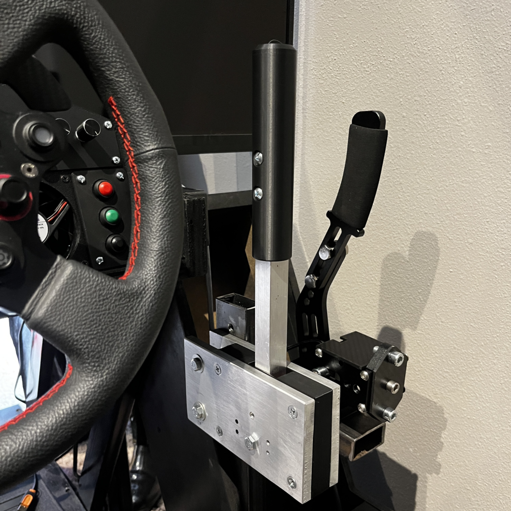
I’ve wanted a sequential shifter for rally games for quite some time, so I decided its time to build one out of some old aluminum stock I had laying around.
Required Tools
- Drill/Drill Press – Drill press preferred, but this project can definitely be done using a hand drill.
- Band Saw – Used to cut the aluminum stock. You can generally have your pieces cut by a local metal supplier if used though.
- 10-24 Tap – Used for the screws holding the handle pieces together.
- Wire Stripper
- Hot Glue Gone
- Screw Driver
- Wrenches
- 3d printer (or a friend with one)
- 1/4″ Drill Bit
- 7/32″ Drill Bit
Required Components
NOTE: All of this links to my Amazon Affiliate store and will provide me some income. This blog is a spendy endeavor and I would appreciate using them to help support these projects and the time it takes to create the writeups!
- 3/8″ x 4″ x 6 1/2″ aluminum flat stock. This can be purchased online, but its usually much cheaper if you can get it locally from a metal supplier.
- 3/4″ x 12″ – aluminum square stock. Length can be adjusted as desired.
- 2x – Micro Switches
- 2x – Die Springs
- 24awg 3 conductor wire – Any 3 conductor wire will do, mine is approximately 1/4″ diameter total to be pinched between the printed halves.
- 2x – Ball Plungers (The ones I used were too small and didn’t offer the correct effect. I will be sourcing replacements and will update when complete.
- Arduino leanardo/micro – I have one of these fully integrated into my rig already and will be using that.
- Simhub software
- 10-24 hardware
- 1/4-20 hardware
First Step – Drill the holes in the aluminum flat stock (x 2)
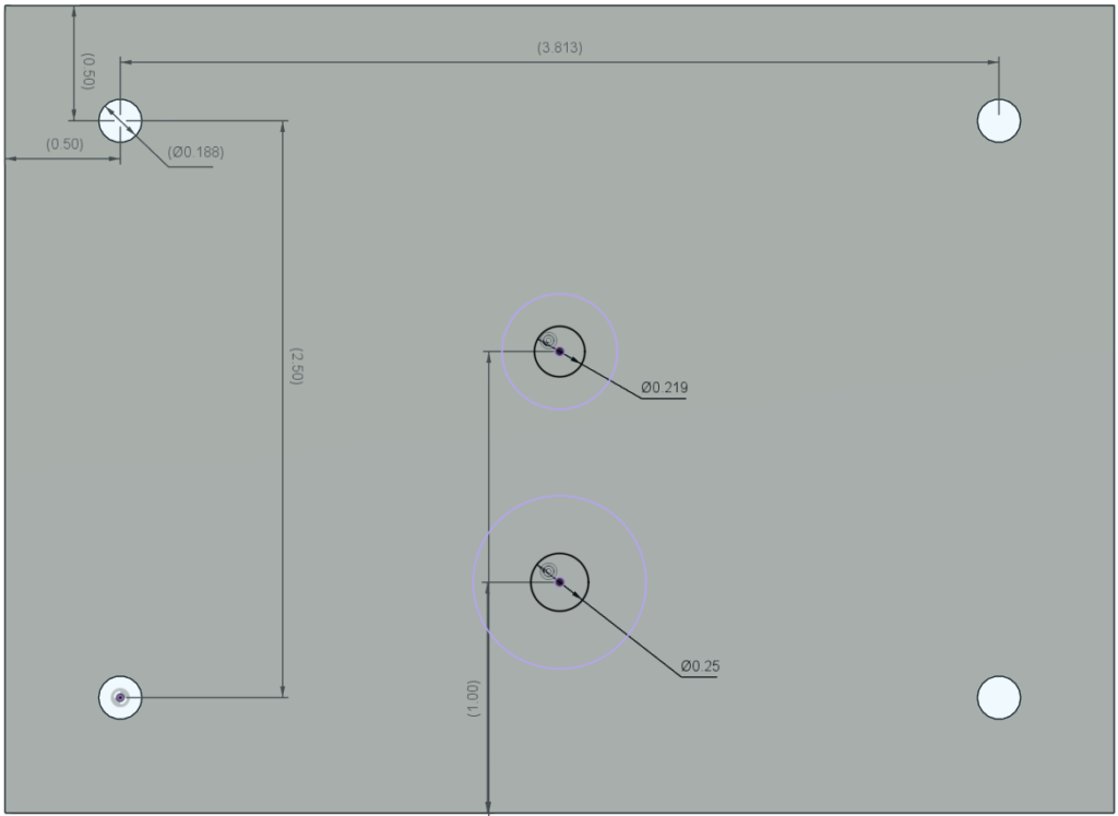
- We start by drilling 4 holes which will be used to bolt the whole sandwich together at the 4 corners. The pattern was 2 1/2 x 3 7/8.” These are drilled with the 7/32″ bit to allow our 10-24 hardware to easily fit through.
- Using the same 7/32″ bit I drilled a whole for the ball plunger (again, this turned out to be too small, so I will update when I get this sorted out.) This is the center hole, 2″ from the bottom
- The center hole, 1″ from the bottom was used to the pivot bolt for the shift handle. 1/4″
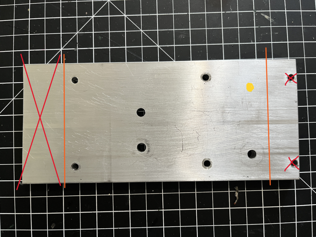
- Unaccounted for in my fusion model, is the two holes used for mounting this contraption, since it was kind of an afterthought for me. Also 1/4″
Since I was reusing some stock, it was not quite the right size. The portions outside the orange lines were eventually cut off. The two far right holes are what I left for mounting to the rig later. (Yellow circle not yet drilled)
The shift lever
First step was to cut this to length. Mine is approximately 12.” The travel/spring pressure at this length feels pretty good, but taking an extra inch off may improve it slightly. Once cut to length, I 3d printed a sleeve to act as my hands contact point. I slid the printed piece on and marked the locations, hit them with a punch then drilled and tapped them. It was then fastened with some 10-24 x 3/8″ button heads.
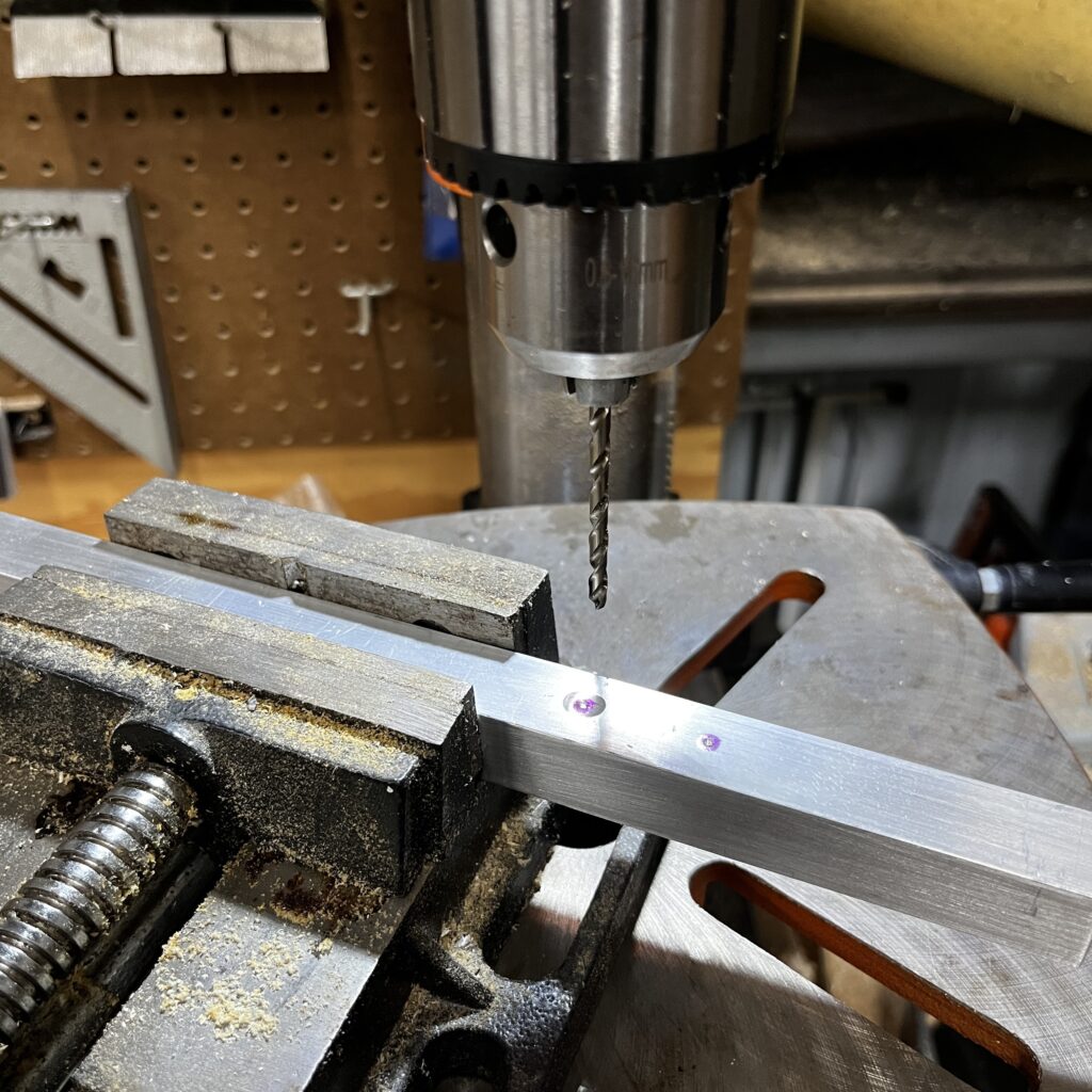
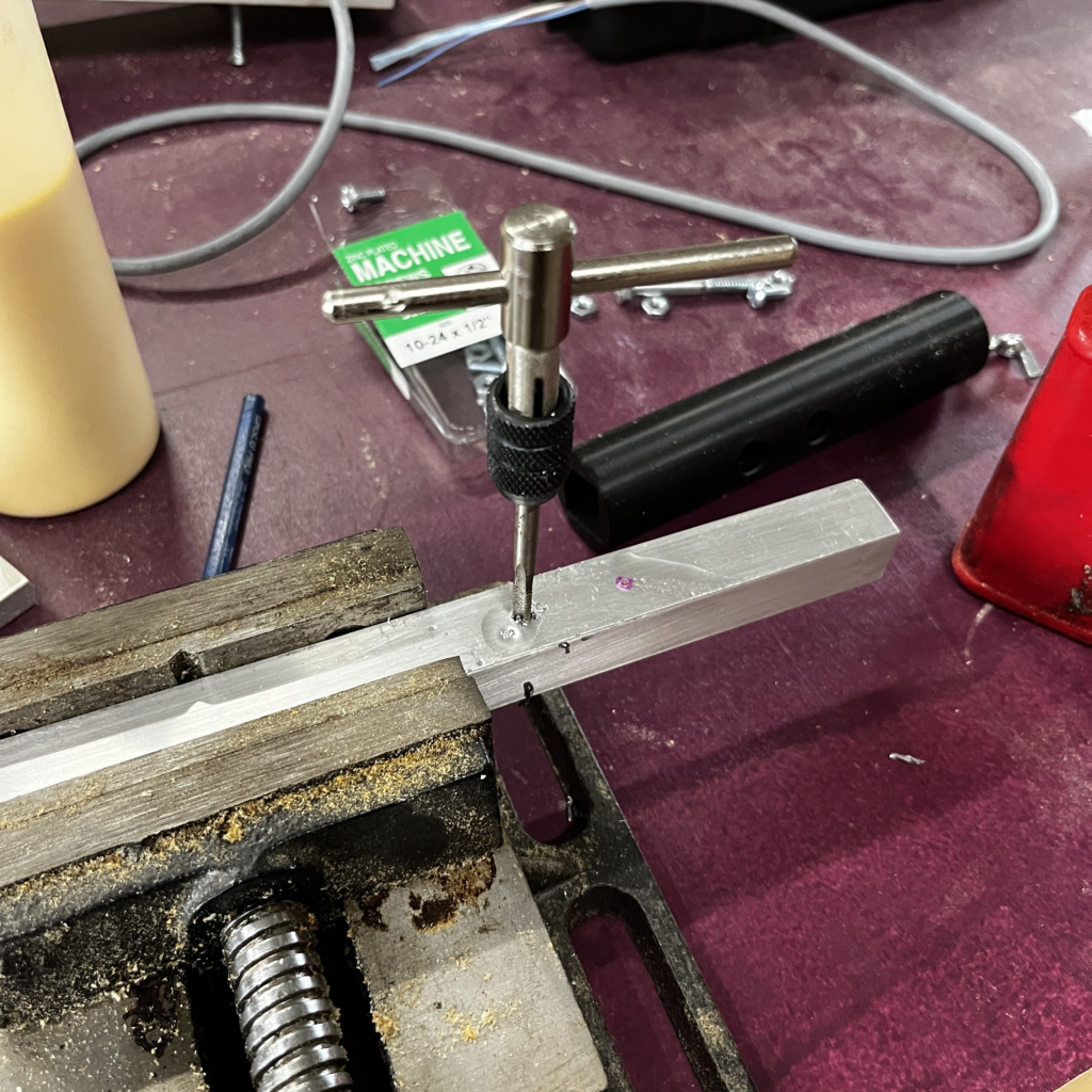
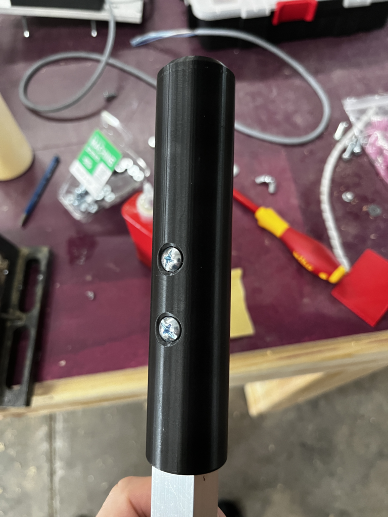
3d printed internal section and electronics
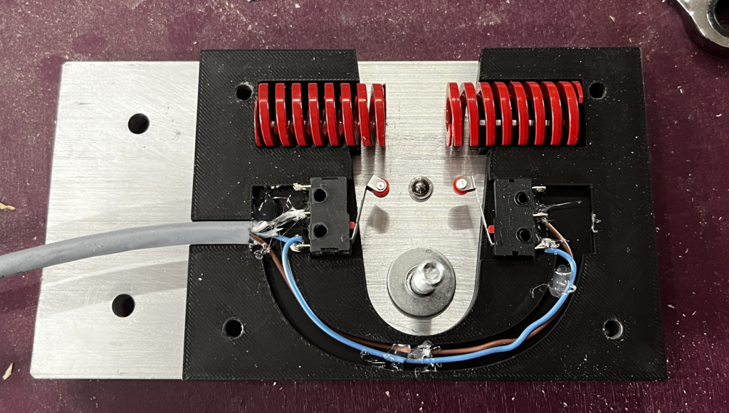
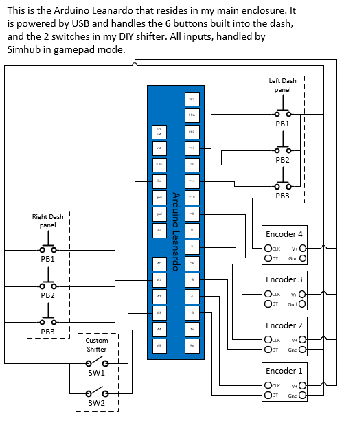
Next I designed the center section to hold all the inside components. This was to hold the pair of micro switches, some internal wire routing and the springs. To wire this, the common pin from each switch was tied together and to the ground of my Arduino. Each switches normally closed contact went to their own inputs on the Arduino. Hot glue was used to hold all this in place during assembly. The ball plunger was glued in place from behind, and the springs just set in.
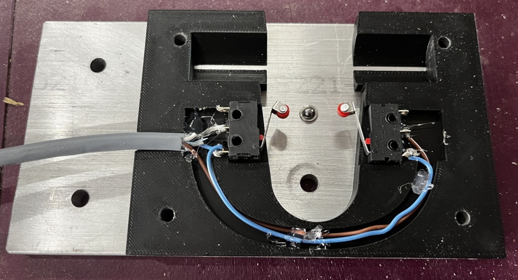
Putting it together
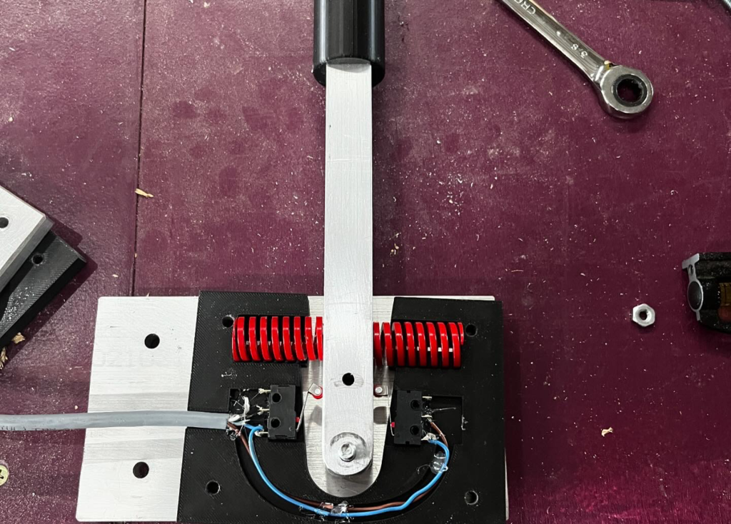
I then put the 1/4″ bolt through to hold everything in place. After adding the other side of the sandwich, I put the 10-24 hardware in to hold the whole thing together. My local big box store who shan’t be named, did not have my preferred button heads at this length, so after assembling, I ended up taking out each screw, and hitting the holes with a countersink bit so they could sit flush.

Making something to mount it to…
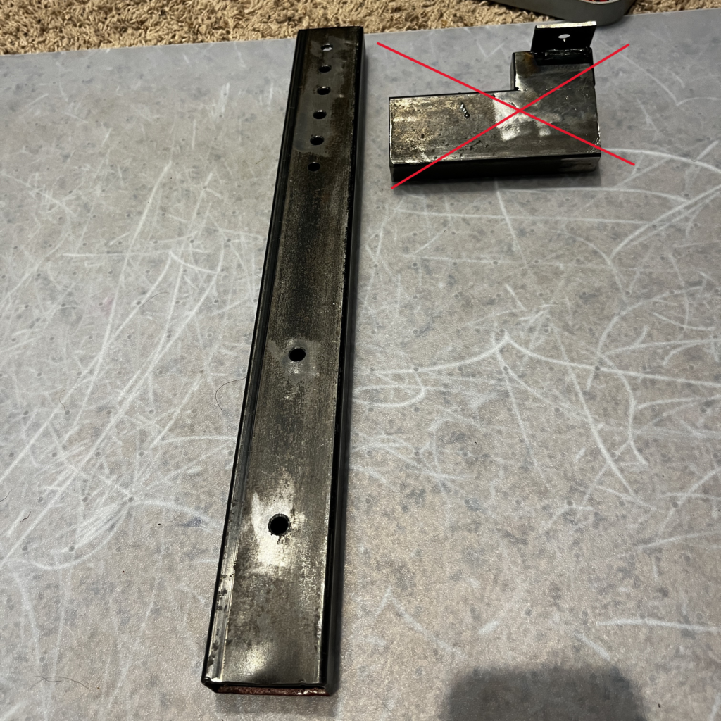
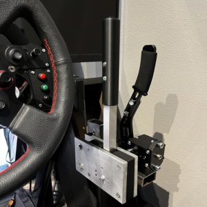
I then realized I didn’t have a clue how I was going to mount this thing. I ended up finding a piece of 1″x2″ tubing in my scrap pile. I drilled holes every inch in this, not quite sure what height I would like it. That was I would be able to move it vertically in 1″ increments. This will also serve to mount a handbrake later. This was then bolted into my makeshift center console using some more 1/4″ bolts. (Ignore the red x piece, this was for the handbrake)
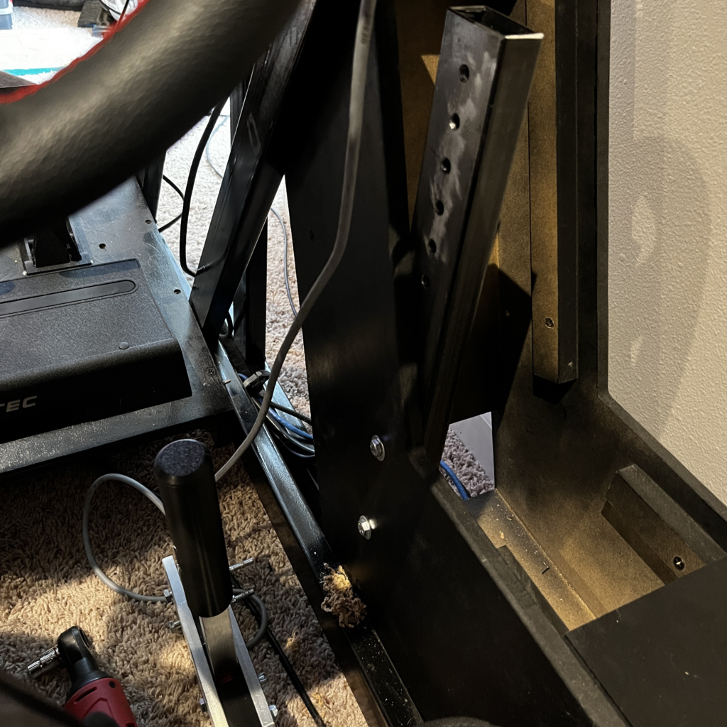
Finally bolted the whole assembly on
Land the wires and use Simhub to get it running
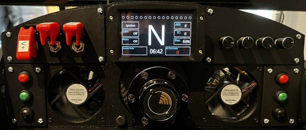
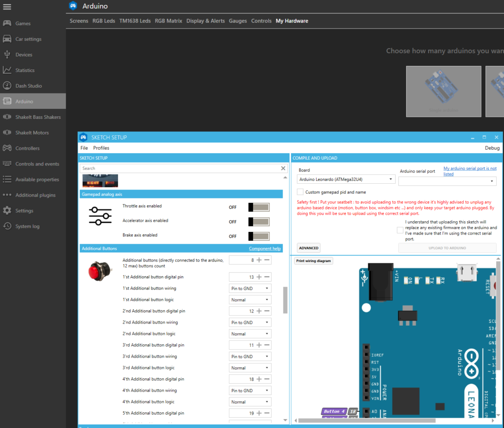
I landed on the same Arduino as used in my custom dash post, so all those components are shown in the wiring diagram as well. Finally, I opened up my Arduino sketch inside Simhub and added these two switches as additional buttons.
Conclusion
I had a lot of things go wrong in this build, so this is more of an informational share as I dial in the design. BUT it is currently in working order and I am using it daily. I hope seeing this done helps somebody out as I work out how to improve it. I will definitely be creating another post for this down the road, where I will be able to share more of the design and assembly process.
Thanks for reading!
