Overview
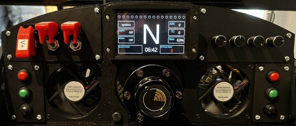
This guide will walk you through how I designed and built my custom sim dashboard. I am mounting to my Simagic Alpha Mini Wheelbase and my custom chassis. With all the electronics housed in this and a need for future modularity, I built a wooden box with a slide off lid, to both mount the wheel, as well as hold all the major electronic components. I wanted this to feel as much like the inside of an actual car as possible when I get in. This means, I didn’t want to be turning on power strips, light switches etc. before sitting down, I just wanted to sit in and flip some toggles like you would in a race car to power everything up.
If there are any details I missed, leave a comment below and I will be sure to add it!
Requirements
- Toggle switch to turn on 120v power for wheel base and shaker power amp
- Toggle switch to turn on USB power to turn on the USB HUB (Vocore, Arduino, Wheel, Nobsound Amp)
- Toggle switch to turn on a pair of 12v PC fans (Hard to race with sweaty hands)
- Modular panels to hold all switches, buttons, encoders, etc. I am indecisive and will without doubt want to move stuff around
Existing Hardware to be incorporated
- Simagic Alpha Mini wheelbase with GTS wheel
- Wheelbase has an 80mm x 80mm bolt pattern on the face that we will be using to attach this assembly to.
- Bass shaker setup
- Nobsound mini power amp
- Dayton Audio – BST1 Transducer
Required Tools
- 3d Printer
- Wire Stripper
- Exacto-Knife
- Screwdrivers
- (Optional) Label printer
- (Optional) Woodworking tools as required for your enclosure
- (Optional) Ferrule Crimper – Im a nut for frayed wires, so this was mandatory for me.
Required Parts
See bottom of the page for links to all parts
- Buttons, toggle switches and Encoders
- A 12v DC power supply. I used a generic 12v 5 amp LED power supply
- 10 amp relay with a 12vdc coil. (Amperage requirements may differ depending on wheel base)
- USB HUB and a USB extension cable.
- Some sort of circuit protection on the 120vac incoming power.
- Terminal blocks, splice connectors or some sort of power distribution hardware.
- Arduino Leanardo or Micro and breakout shield
- 80mm PC Fans (I used 2, one behind each hand)
- 6-32 x 1/2″ machine screws and nuts
- 1/2″ wood screws
- M8 x 10mm Bolts (for attaching assembly to the wheel base)
- Simhub software – Please support this person/team for this incredible piece of software. What they are asking for it is unbelievable low for its functionality.
- 22awg wire – I bough a variety pack.
- Wire Ferrules
3d Printing the parts and assembling into 1 piece
- The printed parts include:
- Main halves of the shell. These are blank shells which we can pick and choose modular plates holding buttons and encoders.
- A top cap, which is made to brace the top portion, and add a little more visual appeal.
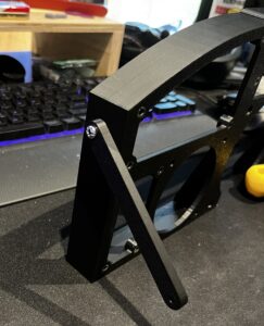
- Two side support straps. I have four bolts in the center which attach to the wheel base and the top cap, but this left the side a little floppy. These are to help support the whole assembly while pushing buttons.
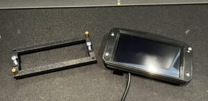
- A mounting backer for my VoCore dash screen.
- Button plate – 1 is shown, and will be similar to the other blank plates. This assembly will include 2 x 3-button plates, 1 x 4 encoder plate, 1 x 3-Toggle switch plate.
- Press in the retaining nuts into the back of the plates. This will allow us to screw on our plates from the front. (I just put a screw in the front and tightened it to pull them in)
- Screw on the Top Cap and side braces.
- Grab the 2 x 80mm PC fans and screw them into place.



Assemble a Button Plate
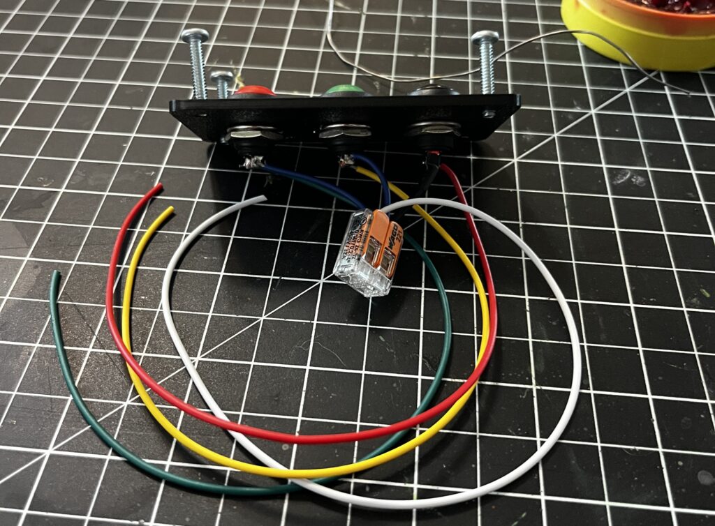
- 1 pin from each button is tied together which will be the common to the Arduino Ground.
- We then solder on a lead for each button. These will go to the Arduino IO pins. (1 for each button)
- Note: These buttons were re-used from my previous setup and already had the ground common wires soldered on. I left them there and used one of my Wago lever nuts to tie them together.
- I built two plates of these, one for the left, and one for the right side of the wheel.
Assemble an Encoder Plate
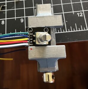
- First step was to remove all the pins that came on the encoders. (Made for the standard breadboard jumper wires) I did this by sticking them in my tiny wish .com vice, heated them with the soldering iron and pulled on them with a plyers.
- Then I soldered on a fresh set of wires. I left about 12″ on here, knowing this plate will be installed right in front of my Arduino’s final home.
- Again I Wago’d the commons together and added a lead to that.
- Crimped on all my ferrules
- Lastly, Label them so its easy to land them on the Arduino later.


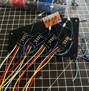
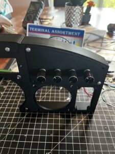
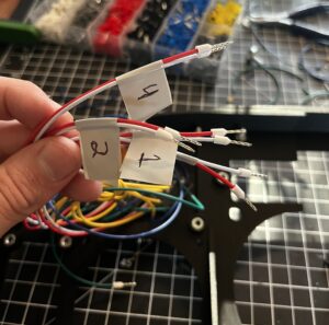
Progress capture with all but the toggle plate
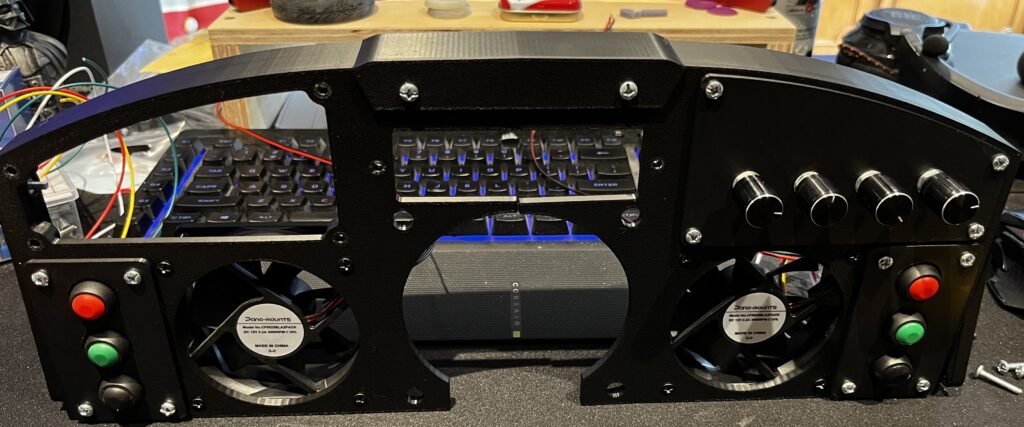
Assembling the Toggle switch plate
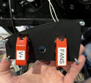
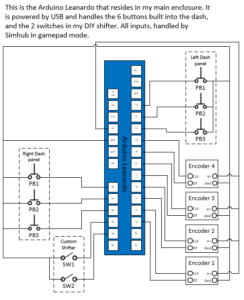
- Switches went into the plate easily and are wired per the diagram found below.
- The V+ has a wire coming from my always on 12vdc power supply, and runs to the relay to switch the 120vac.
- Fan switch comes off the 12vdc power supply and is wired directly to the two PC fans (in Parallel)
- The franken-switch…. The USB power cable. I made this long ago and didn’t dare take the electrical tape back off for a photo, but I used the process as follows.
- Using an Exacto knife, I very carefully sliced (the long way) about 3 inches down a USB extension cable. This exposed the 4 wires inside.
- Using a color code I found on the google machine, I cut the v+ wire, and connected each side to one side of the switch.
- Then taped it to all frick-snacks and hoped I never had to take this apart.

Mounting the VoCore
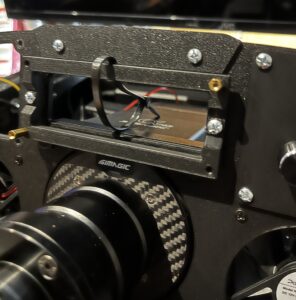
- This is another component salvaged from a previous assembly. I found the original case for the screen on Thingiverse. I didn’t feel like futzing with it, so I just made a transition bracket to attach to the front of this dash.
- At this point I had the whole thing attached to my wheel base, and realized I didn’t think of wire management, so that’s what the zip tie is here for…
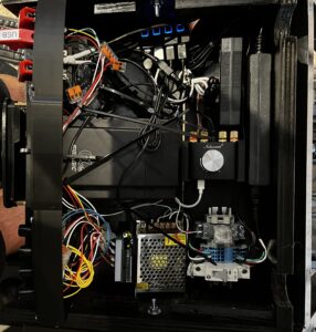
Time to start putting it ALL together now…
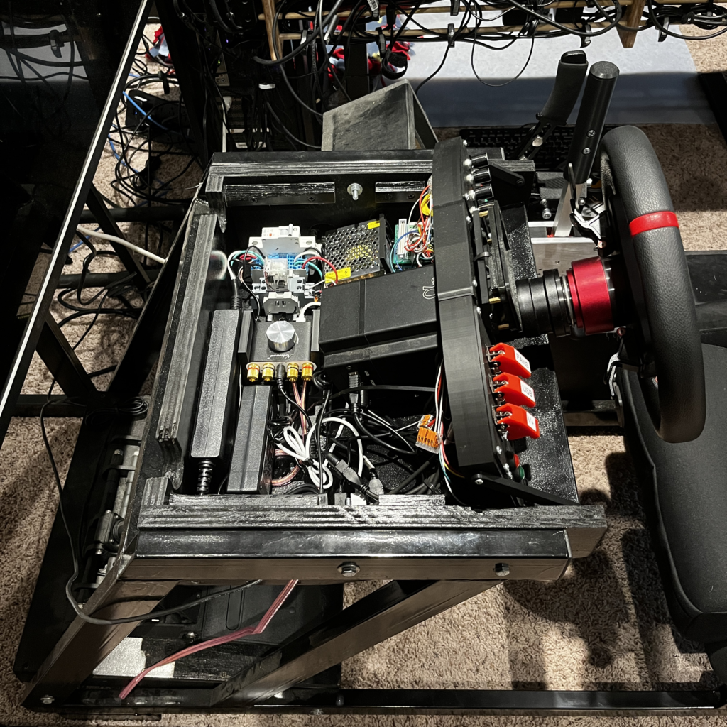
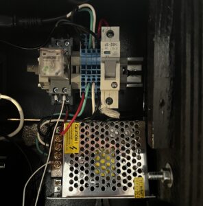
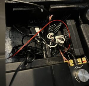
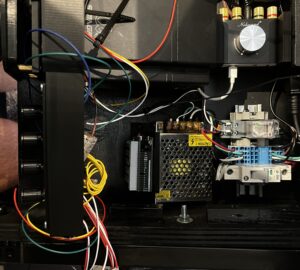
- First up is the power supply section. This is made up of components I accessed from a previous professional life.
- The whole assembly is mounted on a short piece of DIN rail.
- The 10 amp breaker. This is an Allen Bradley 10amp breaker.
- My friends at Wago were good to me, if you haven’t been able to tell from my previous Wago plugs. The blue terminal blocks here handle distributing my 120vac power.
- Finally on the end, a 12vdc relay, sourced in a two pack from amazon.
- The 12vdc power supply sits next to this section, and powers the 120vac relay and my PC fans.
- I cut the plugs off of the power bricks for my Nobsound amp and my wheels power supply and landed in the terminal blocks as well, so I didnt have to force a power strip in here as well. If I did it again, I would make the box bigger, and probably use the relay to switch a power strip instead.
- The Nobsound amp is in a 3d printed stack stand, since I am planning on adding a second one for more bass transducers.
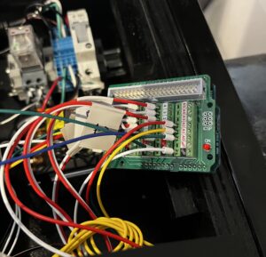
- Landed all the wiring from the buttons and encoders on the arduino.
- One image shows the Arduino installed in a snap in vertical holder. (Found in bambu studio?)

Setting it up in Simhub
Again, I can’t say enough about this software. This person/team has done an incredible job in creating an all encompassing sim racing extension for us. Please visit their site, and support them if you can. They are nice enough to give this software away for free, but if you can afford to support them to get the full version, please do!
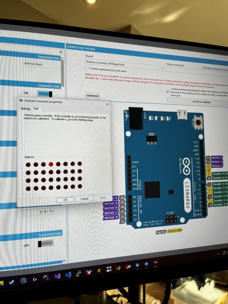
There are lots of videos on setting this up, so I wont go into too much detail here, but this shows my Pinout and I have the windows joystick window up testing my buttons post upload.
The electrical drawings…

…AAAAAAAAAAAnd its done!

Parts Links
NOTE: All of this links are to my Amazon Affiliate store and will provide me some income. This blog is a spendy endeavor and I would appreciate using them to help support these projects and the time it takes to create the writeups!
Arduino leanardo – https://amzn.to/46llFti
Breakout shield – https://amzn.to/3y3SRce
Push Buttons – https://amzn.to/4cTwFAt
Encoders – https://amzn.to/4cSSGj1
Toggle Switches – https://amzn.to/4fgTuzM
12vdc power supply – https://amzn.to/46ne4KA
Nobsound amp – https://amzn.to/4dzO4OT
Dayton BST1 Bass Transducer – https://amzn.to/4dhM4dS
12vdc relay – https://amzn.to/4cSSPD5
Wire Ferrule Kit – https://amzn.to/4dgaWmd
Wire – https://amzn.to/4bXyPxW
Machine Screws – https://amzn.to/3Yq80Pw
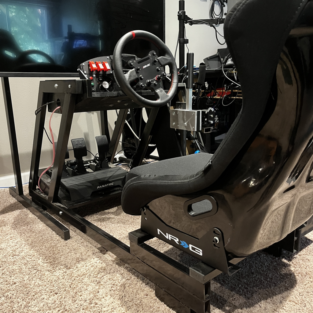
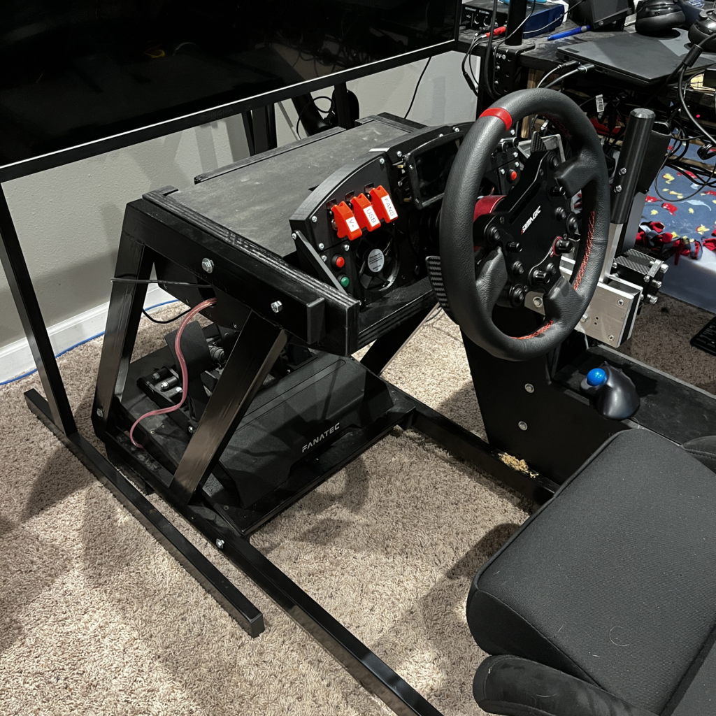
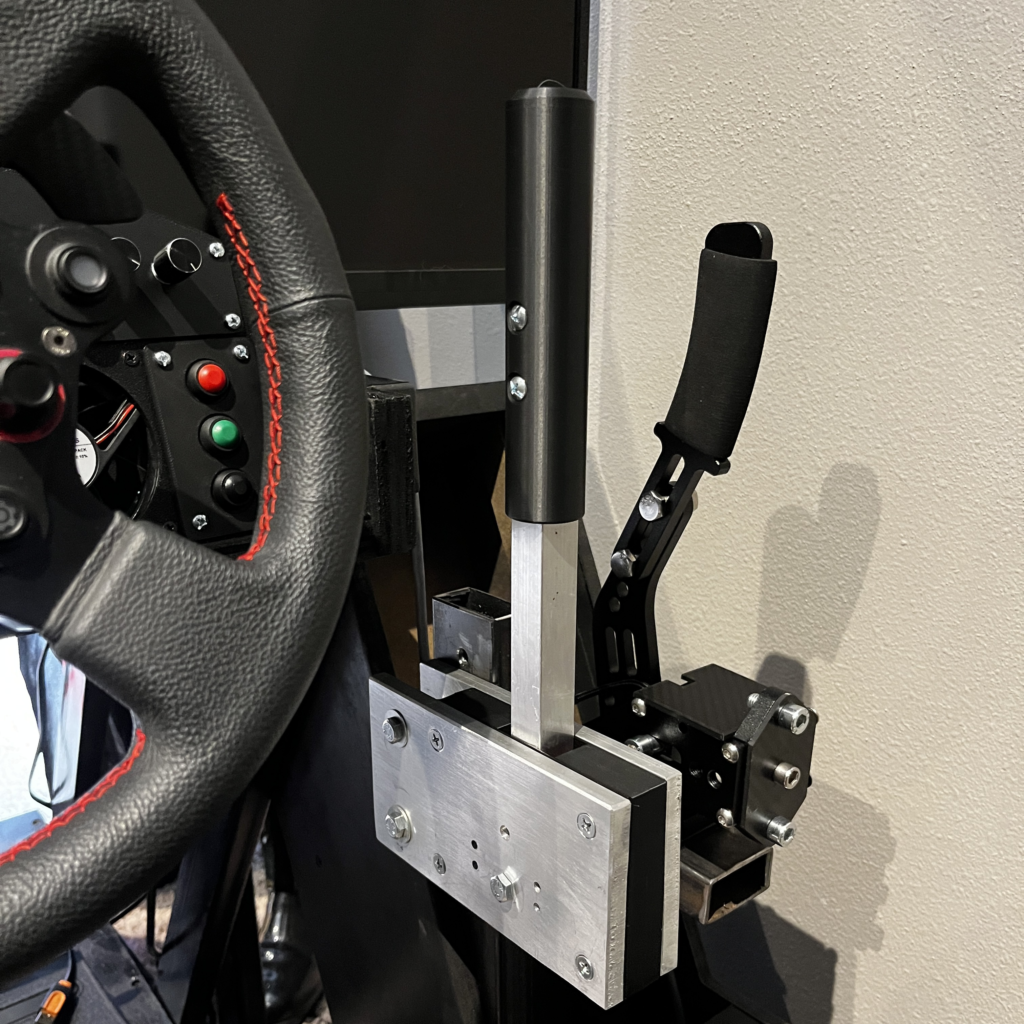
Some pictures of the full rig
